
The Talimarjan Gas-Fired Combined Cycle Power Plant in Uzbekistan combines gas turbines with a steam cycle to generate electricity. Devpan supplied Dev24/36 medium-voltage switchgear, the auxiliary main distribution and MCCs.

Electrical Profile of the Project
- LocationUzbekistan
- Building typePower plant
- Installed power≈ 10,000 kVA
- Transformer configuration4 × 2,500 kVA
- Main busbar rated current2 × 4,000 A
- Short-time withstand current (Icw)80 kA / 1 s
- Devpan scopeMedium voltage switchgear, low voltage switchboards and engineering
- Verification standardIEC 61439-1, IEC 61439-2
About the Project
In a combined cycle plant, the auxiliary power system feeds the loads that keep the units running: boiler feed pumps, cooling tower fans, lube oil and fuel gas systems. A loss of supply to these auxiliaries can trip a unit and take generation off the grid. Very hot summers, cold winters, dust and continuous duty all call for extra margin when selecting switchgear and control equipment.
For a plant of this scale, a typical architecture builds the 10 kV auxiliary bus with Dev24/36 metal-enclosed modular switchgear and feeds a 2 × 4,000 A low-voltage main distribution through four 2,500 kVA transformers. Auxiliary motors are grouped in redundant A/B trains in Form 4b, IP54 DevControl MCCs. Two 1,500 kVA emergency generators cover safe shutdown and restart loads, while DevComp panels balance reactive power.
Devpan Scope and Switchboard Architecture
Devpan’s scope extends from the 10 kV auxiliary distribution to the motors of the plant’s auxiliary systems.
- Medium-voltage switchgear (Dev24/36): metal-enclosed modular panels with 24 kV insulation, operated at 10 kV, for transformer and large motor feeders.
- Main distribution boards (DevPanel): 2 × 4,000 A, 80 kA / 1 s, Form 4b, auxiliary distribution with bus coupler.
- Motor control centres (DevControl): IP54, withdrawable, redundant A/B trains for feedwater, cooling, lube oil and fuel gas systems.
- Power factor correction (DevComp): stepped compensation for auxiliary motor loads.
- Sub-distribution boards (DevBox): control building, workshop and ancillary buildings.
Technical Configuration
| Installed power | ≈ 10,000 kVA |
|---|---|
| Transformer configuration | 4 × 2,500 kVA |
| Medium voltage level | 10 kV (Dev24/36) |
| Low voltage / frequency | 400 / 230 V, 50 Hz |
| Main busbar rated current | 2 × 4,000 A |
| Short-time withstand current (Icw) | 80 kA / 1 s |
| Form of internal separation | Form 4b |
| Degree of protection (IP) | IP54 |
| Generator back-up | 2 × 1,500 kVA |
| Verification standard | IEC 61439-1, IEC 61439-2 |
Devpan Products Used in This Project
Project-Specific Engineering Topics
Redundant A/B auxiliaries
Duty and standby pumps and fans are fed from different sections, so a single busbar fault does not stop the unit.
Safe shutdown supplies
Lube oil, turning gear and emergency cooling loads are fed from a generator-backed emergency section.
Short-circuit withstand
Large auxiliary transformers produce high fault currents; busbars rated 80 kA / 1 s are selected accordingly.
Harsh site conditions
IP54 enclosures protect against dust and temperature swings and improve reliability under continuous duty.
Frequently Asked Questions
What is the auxiliary power for the Talimarjan plant?
For a combined cycle plant of this scale the auxiliary installed power is approximately 10,000 kVA, with a typical transformer configuration of 4 × 2,500 kVA. The LV main busbar is planned at 2 × 4,000 A and 80 kA / 1 s, MV distribution at 10 kV uses Dev24/36 switchgear, and emergency power comes from 2 × 1,500 kVA generators.
Why use Dev24/36 switchgear on a 10 kV system?
A 24 kV insulation level gives a generous margin at 10 kV operation, which translates into long service life and high operational safety in a dusty, hot plant environment.
Why are auxiliary motors split into A/B trains?
Feeding redundant pumps and fans from separate sections ensures that a single board or busbar fault cannot halt generation.
Similar Reference Projects
 Akkuyu Nuclear Power Plant, MersinPower plant · Mersin, Türkiye
 Montenegro Power PlantPower plant · Montenegro
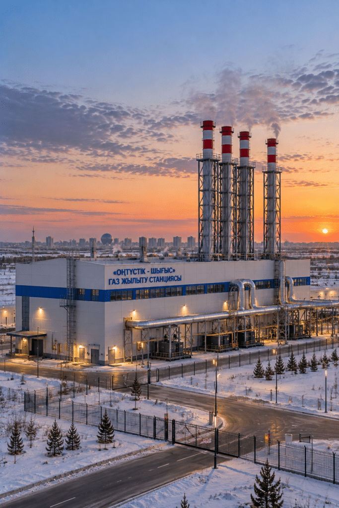 Astana Gas-Fired Boiler HousePower plant · Astana, Kazakhstan
Do you have a project of a similar scale?
Send us your single-line diagram, your transformer rating or simply your load list. Our engineering team runs the short-circuit and discrimination study and defines the form of separation and busbar cross-section with you.
Request a quotation