
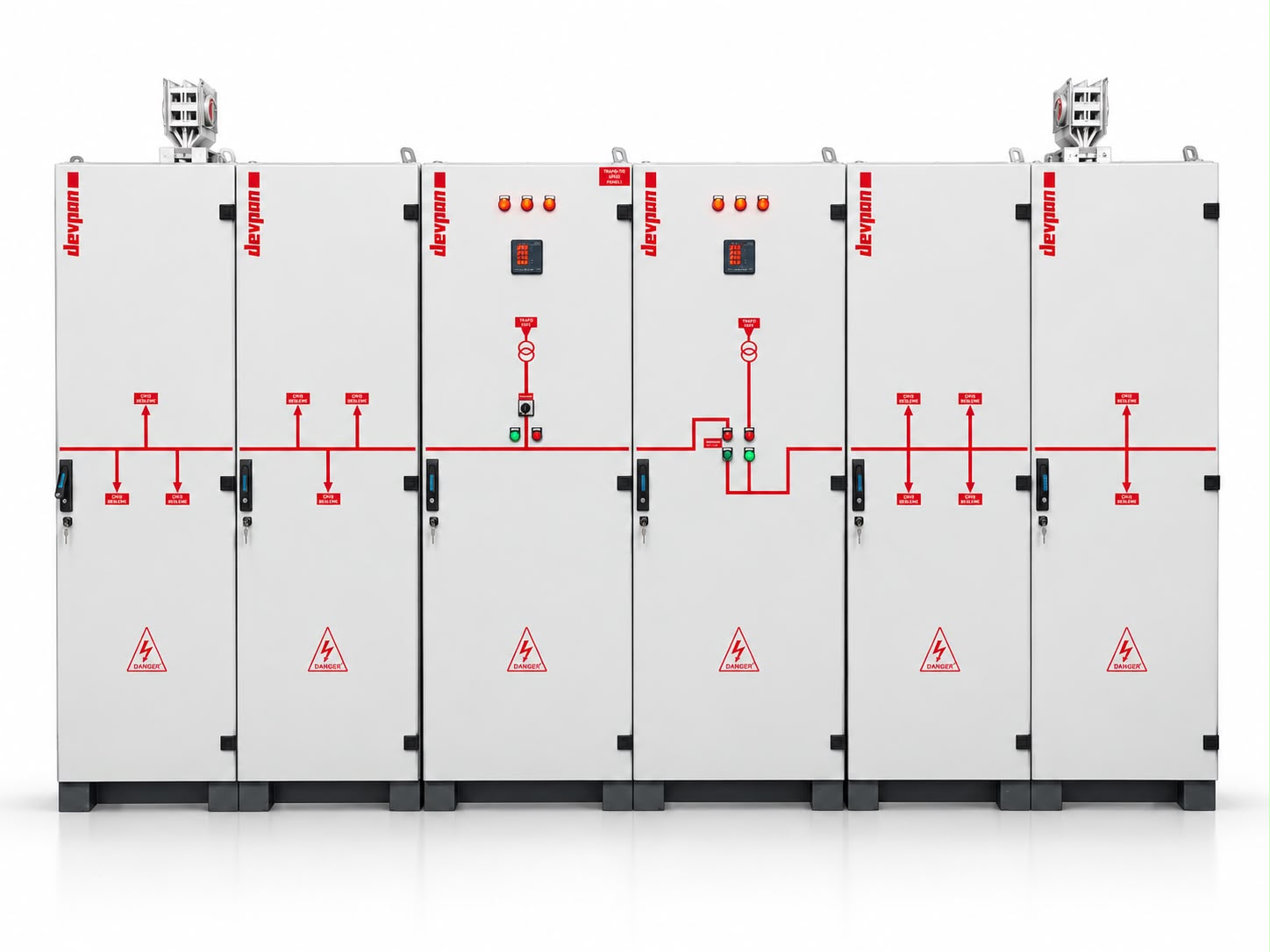
DevComp power factor correction panels (PFC) are low voltage switchboards that correct the power factor (cos φ) by compensating, with capacitor steps, the reactive power the facility draws from the grid. They are designed in the 12.5 – 1000 kVAr range, with contactor-switched (standard) or thyristor-switched (dynamic) steps, and with detuned reactors in facilities with harmonic loads.
What Is a Power Factor Correction Panel and Why Is It Needed?

Inductive loads such as motors, transformers and ballasts draw reactive power from the grid to build up their magnetic fields. This power does no useful work, yet it flows as real current through cables and transformers, causing losses, and is billed by the utility. A power factor correction panel generates the required reactive power within the facility, so this current no longer has to be drawn from the grid.
In DevComp panels, the reactive power control relay reads the instantaneous cos φ and current from the network and switches the required steps in or out. Steps are switched by contactors; for rapidly changing loads, however, thyristor (static) switching is preferred to eliminate mechanical wear and switching delay.
In installations with many nonlinear loads (frequency converters, UPS units, LED drivers, welding machines), capacitors can resonate with the network impedance. To eliminate this risk, detuned reactors are connected in series with the steps; this shifts the resonance frequency below the harmonic range and protects capacitor life.
Technical Specifications
DevComp power factor correction panels are configured according to the facility’s load profile and harmonic level. The table below summarizes standard and optional equipment.
| Property | Value / Option |
|---|---|
| Applicable standard | IEC 61439-1, IEC 61439-2; IEC 61921 for power capacitor banks |
| Reactive power range | 12.5 – 1000 kVAr (multiple panels for higher ratings) |
| Capacitor type | Self-healing, dry-type; cylindrical or box-type |
| Step switching | Capacitor-duty contactor (with pre-charge resistors to limit inrush current) or thyristor module |
| Control | Reactive power control relay; models with harmonic measurement and communication optional |
| Detuned reactor | p = 7% or p = 14%; iron-core, with thermal protection |
| Step protection | Fused switch-disconnector or molded case circuit breaker per step |
| Thermal management | Thermostat-controlled filtered fans, planned air inlet and outlet, internal temperature monitoring |
| Measurement and display | cos φ, voltage, current, THD and step status display |
| Communication | Modbus RTU (optional), alarm output |
| Mounting | Floor-standing enclosure, placed next to the main switchboard or in a separate compensation room |
| Enclosure | Cold-rolled (DKP) sheet steel; electrostatic powder coating RAL 7035 |
| IP rating | IP31 / IP41 / IP54 |
| Maintenance support | Capacitance measurement, step testing and capacitor replacement |
The values given are typical application ranges; final ratings are determined after the single-line diagram, short-circuit and selectivity calculations.
Four Critical Decisions in Power Factor Correction Design
Contactor- or thyristor-switched?
Where the load changes slowly, contactor-switched compensation is both sufficient and economical. For loads that change within seconds, however, such as presses, cranes, elevators and welding machines, contactors cannot keep up and wear out quickly; in these installations, thyristor-switched (dynamic) compensation is preferred.
Harmonic analysis and reactor selection
As the share of drives, UPS units and LED drivers increases, harmonic distortion also increases. Installing capacitors without a measurement-based harmonic analysis leads to rapid capacitor overheating and step failures. Based on the measurement results, a p = 7% or p = 14% reactor is selected.
Step plan and resolution
Dividing the total kVAr into a few large steps reduces cost but makes precise correction impossible. A graded plan starting with small initial steps keeps cos φ at the target value even at low loads.
Operation, heat and maintenance
Capacitors are sensitive to heat; keeping the temperature inside the panel under control directly affects their service life. During annual maintenance, step capacitance is measured and contactor contacts and reactor temperatures are checked.
Where Are Power Factor Correction Panels Used?
Every facility with a high inductive load that pays for reactive energy needs a power factor correction panel. As harmonic levels rise, detuned or dynamic solutions come to the fore.
- Production facilities and factories
- Shopping malls and mixed-use projects
- Hospitals and healthcare facilities
- Data centers and UPS-intensive facilities
- Water and wastewater treatment plants
- Cold storage facilities and logistics centers
- Hotels and business centers
- Workshops with presses, cranes and welding lines
Relevant Technical Information
Frequently Asked Questions
What is the purpose of a power factor correction panel?
A power factor correction panel uses capacitors to generate on site the reactive power required by the facility’s inductive loads. This reduces the apparent current drawn from the grid, lowers cable and transformer losses, reduces voltage drop and eliminates reactive energy charges. It also allows more active power to be carried within the existing transformer and cable capacity.
How many kVAr of compensation does my facility need?
The required kVAr is calculated from the facility’s active power, its current power factor and the target power factor. For accurate results, measuring with a power quality analyzer over several days is far more reliable than relying on utility bills alone. The measurement also reveals the harmonic level.
Which facilities need thyristor-switched compensation?
It is needed where the load changes within seconds or milliseconds: press lines, cranes and hoists, elevator groups, spot welding machines, saw and crusher groups. In these applications, contactor-switched systems both lag behind and wear out quickly due to frequent switching.
Should a detuned reactor with p = 7% or p = 14% be selected?
The choice depends on the dominant harmonic in the facility. In typical industrial facilities where the 5th harmonic dominates, p = 7% (tuned to about 189 Hz) is the common solution. Where the 3rd harmonic is also significant and there are many single-phase electronic loads, p = 14% (about 134 Hz) is preferred. The decision is based on a measurement-based harmonic analysis.
Other Low Voltage Switchboards


Share your network measurements and let’s choose the right compensation solution together
If you know your power factor, harmonic level and load characteristics, we can determine the step plan, reactor ratio and switching type together. For the main distribution side, see the DevPanel page.
Request a quote