
Wind Turbine Electrical Panel: Tower Distribution, Protection and Lightning
wind turbine panel: Wind turbine electrical panels distribute power and control between the nacelle and the tower base and are designed to operate under continuous vibration, wide temperature swings and a high exposure to lightning.
Contents
Electrically a wind turbine is a generating plant that never stops moving and sits high above the ground. The nacelle rotates with yaw, the tower sways, temperature varies widely through the day and the blade tips are the most probable lightning target. Under these conditions panels are conceived differently from onshore industrial boards, particularly regarding vibration withstand, cable movement allowance, condensation control and lightning current management.
Panel architecture inside a turbine
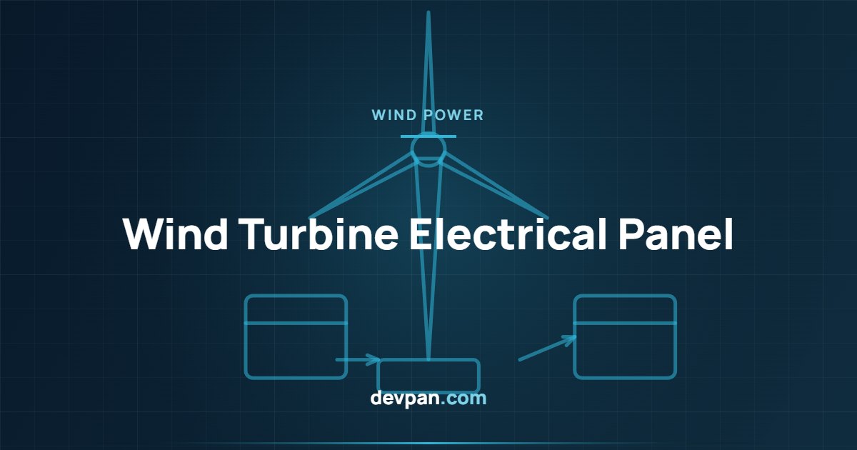
A typical turbine holds three panel groups. The nacelle panel manages the generator, pitch and yaw drives, cooling and sensors. The tower base panel houses the main breaker, auxiliary supplies, lighting, the service lift and socket outlets. The converter panel adapts generator output to grid frequency. Power and communication between these groups pass through a twistable cable loop that accommodates yaw movement.
Vibration, movement and mechanical strength
The tower and nacelle generate continuous vibration. Whether spring clamp or screw type, terminals must be of a vibration tested design and cable bundles have to be fixed at regular intervals. Heavy devices receive additional mounting reinforcement, and door hinges and latches are secured against loosening. The cable support system is arranged so that the yaw loop can move without exceeding its torsion limits.
Lightning protection and equipotential bonding
IEC 61400-24 addresses turbine lightning protection as a dedicated standard. Current captured by the blade tip receptors travels through the hub and nacelle into the tower structure and down to the foundation earth. On the panel side the task is to prevent that current from entering control circuits: coordinated SPD stages, short and direct bonding conductors, screened signal cables and screens earthed at both ends all serve this purpose.
Power quality and grid connection
| Topic | Typical requirement | Reason |
|---|---|---|
| Vibration | Tested terminals and mounting | Continuous mechanical stress |
| Lightning | Coordinated SPD, short bonds | Blade tips are a direct target |
| Condensation | Heater with hygrostat | High humidity inside the tower |
| Corrosion | C4 or C5-M coating | Coastal and offshore salt mist |
| Monitoring | SCADA and event logging | Access is hard, diagnosis is remote |
In full converter turbines the output current is switched, so harmonic and high frequency components must be filtered. At the point of connection, reactive power support, fault ride through behaviour and frequency response are parameterised to the network operator specification. The metering and energy monitoring panel forwards generation data and event records to the plant SCADA system.
Climate, condensation and maintenance
Relative humidity inside the tower can be high, so anti condensation heaters with hygrostats are standard practice to protect electronic boards. Coastal and offshore sites require a C4 or C5-M paint system and appropriate sealing against salt mist corrosion. Because maintenance access is difficult, remote diagnostics, stored event logs and standardised spare parts should be planned at design stage.
Key takeaways: wind turbine panel
- Vibration is a primary design input — it governs terminal and mounting selection.
- Lightning current must stay out of control circuits — coordinated SPDs and short bonds are essential.
- The yaw loop needs movement allowance — exceeding torsion limits shortens cable life sharply.
- Remote diagnostics is a necessity — site access is costly and weather dependent.
- Standard source — IEC publication catalogue: iec.ch.
Frequently asked questions
Which SPD types are used in a wind turbine panel?
Type 1 impulse current arresters are applied at the tower base and nacelle entries, with Type 2 and Type 3 stages ahead of sensitive electronics. Coordination distance or decoupling inductance between stages follows the manufacturer data.
How does panel design change for offshore turbines?
Salt mist corrosion, higher humidity and difficult access lead to a higher degree of protection, a stronger coating system and reinforced internal climate control. Redundancy and remote maintenance capability also become more critical.
Do turbine panels follow the standard low voltage assembly standard?
The EN 61439 series remains the base reference for low voltage assemblies, but turbine specific environmental, lightning and safety requirements are assessed together with the IEC 61400 series.
Related articles
- Solar PV Panels: DC String Protection, DC SPD and AC Distribution
- VFD Panel Design: EMC, Filters and Thermal Management
- Energy Monitoring in Switchgear: Meters, Modbus and SCADA Integration
- All technical articles
Do you need tower base, nacelle or connection point panels for your wind farm? Devpan designs the solution around your site climate and lightning data. Related Devpan solution: medium voltage switchgear.

