
EllaLink Data Centre Nouadhibou is a data centre facility in Nouadhibou on Mauritania’s Atlantic coast. Devpan supplied the A/B main distribution, cooling MCCs and power factor correction panels.

Electrical Profile of the Project
- LocationNouadhibou, Mauritania
- Building typeData centre
- Installed power≈ 3,200 kVA
- Transformer configuration2 × 1,600 kVA
- Main busbar rated current2 × 2,500 A
- Short-time withstand current (Icw)65 kA / 1 s
- Devpan scopeLow voltage switchboards, engineering and site coordination
- Verification standardIEC 61439-1, IEC 61439-2
About the Project
In a data centre, continuity is the only measure of an electrical system that really matters; servers and network equipment cannot tolerate even a few milliseconds of interruption. Nouadhibou adds its own conditions: an Atlantic shoreline bordered by desert, with high temperatures, fine wind-blown dust and salty air. Cooling demand stays high all year, and voltage events on the utility side can call the UPS and generator systems into action more often than in milder climates.
For a data centre of this scale, the typical approach is a 33 kV medium-voltage supply feeding approximately 2 × 1,600 kVA transformers and two fully independent A and B distribution paths. Each path carries a main busbar of about 2,500 A that feeds its own UPS system and rack distribution, while a generator of around 1,000 kVA carries the site through extended outages. Form 3b to Form 4a separation keeps the other path and neighbouring units live during work on any single outgoing circuit.
Devpan Scope and Switchboard Architecture
Devpan’s scope covers the low-voltage distribution from the transformer terminals to white-space rack supplies and the cooling plant.
- Main distribution boards (DevPanel): typically 2 × 2,500 A for A and B paths, 65 kA / 1 s, with generator and UPS incomers and outgoers.
- Sub-distribution boards (DevBox): white-space, PDU feeder and technical room boards, IP31 – IP41.
- Motor control centres (DevControl): drive-based MCCs for chillers, CRAH units and pumps.
- Power factor correction (DevComp): detuned reactive power compensation for the cooling loads.
Technical Configuration
| Installed power | ≈ 3,200 kVA |
|---|---|
| Transformer configuration | 2 × 1,600 kVA |
| Medium voltage level | 33 kV |
| Low voltage / frequency | 400 / 230 V, 50 Hz |
| Main busbar rated current | 2 × 2,500 A |
| Short-time withstand current (Icw) | 65 kA / 1 s |
| Form of internal separation | Form 3b – Form 4a |
| Degree of protection (IP) | IP31 – IP41 |
| Generator back-up | 1 × 1,000 kVA |
| Verification standard | IEC 61439-1, IEC 61439-2 |
Devpan Products Used in This Project
Project-Specific Engineering Topics
Independent A/B paths
Every IT rack is fed from two separate distribution paths, so maintenance or a fault on one path leaves the load running on the other.
Dust and salt protection
Filtered, positively pressurised ventilation in switchrooms limits how much salty, dusty outside air reaches busbar joints.
Selectivity and arc safety
Breaker coordination ensures a rack-level fault never trips upstream distribution, while internal separation and closed-door operation reduce arc-flash exposure.
Energy metering
Per-feeder metering separates IT and cooling consumption, making it straightforward to track efficiency indicators such as PUE.
Frequently Asked Questions
What is the installed power for a data centre of this scale in Nouadhibou?
For a data centre of this scale the installed power is approximately 3,200 kVA, with a typical transformer configuration of 2 × 1,600 kVA. The main busbars are typically 2 × 2,500 A rated 65 kA / 1 s, supplied at 33 kV, with a generator of around 1,000 kVA providing standby power.
Why does a data centre need two separate distribution paths?
A single path means that maintenance or one fault stops the whole IT load. An A/B architecture lets dual-corded equipment keep running when either path is lost.
How do the UPS and generator work together?
When the grid fails, the UPS carries the load from its batteries; the generator starts within seconds, stabilises and takes over, after which the batteries are recharged.
Similar Reference Projects
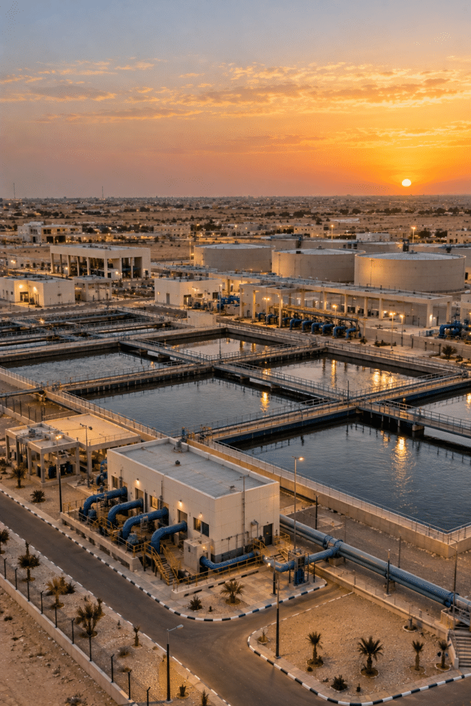 Nouakchott Water Treatment PlantWater treatment plant · Nouakchott, Mauritania
 Kiffa SubstationSwitchyard and substation · Kiffa, Mauritania
 Nizhny Novgorod IT CampusTechnology campus · Nizhny Novgorod, Russia
Do you have a project of a similar scale?
Send us your single-line diagram, your transformer rating or simply your load list. Our engineering team runs the short-circuit and discrimination study and defines the form of separation and busbar cross-section with you.
Request a quotation