
The Dragon Oil Project is an oil and gas facility in Turkmenistan. Devpan supplied motor control centres, main distribution, power factor correction and sub-distribution boards for the project.

Electrical Profile of the Project
- LocationTurkmenistan
- Building typeOil and gas facility
- Installed power≈ 5,000 kVA
- Transformer configuration2 × 2,500 kVA
- Main busbar rated current2 × 4,000 A
- Short-time withstand current (Icw)80 kA / 1 s
- Devpan scopeLow voltage switchboards, engineering and site coordination
- Verification standardIEC 61439-1, IEC 61439-2
About the Project
In oil and gas facilities, most of the electrical load consists of pump, compressor and fan motors, and an unexpected motor trip means not only lost production but also a process safety risk. Large transformers and high motor contribution push up fault levels, which makes busbar and breaker selection more demanding. Ambient conditions such as heat, dust and saline air require switchboards to be located in safe-area, air-conditioned rooms and built with a high degree of protection.
At this scale a typical configuration uses approximately 2 × 2,500 kVA transformers fed from the 10 kV network. DevPanel boards with a 2 × 4,000 A main busbar and 80 kA / 1 s withstand operate as two half-busbars with a coupler. Form 4b DevControl MCCs with withdrawable or removable motor feeders allow one outgoing unit to be maintained while the rest of the process keeps running. DevComp panels correct the power factor of motor loads, and generators of around 2 × 1,250 kVA support safety and emergency shutdown systems.
Devpan Scope and Switchboard Architecture
Devpan’s scope covers low-voltage distribution from the transformer outputs to process motors and auxiliary services.
- Motor control centres (DevControl): Form 4b, IP54; VSD, soft-starter and direct-on-line feeders for pump, compressor and fan motors.
- Main distribution boards (DevPanel): 2 × 4,000 A main busbar, 80 kA / 1 s, bus coupler and generator changeover.
- Power factor correction (DevComp): harmonic-filtered, automatic stepped compensation for motor-dominated process loads.
- Sub-distribution boards (DevBox): control building, laboratory, workshop, lighting and trace heating supplies.
Technical Configuration
| Installed power | ≈ 5,000 kVA |
|---|---|
| Transformer configuration | 2 × 2,500 kVA |
| Medium voltage level | 10 kV |
| Low voltage / frequency | 400 / 230 V, 50 Hz |
| Main busbar rated current | 2 × 4,000 A |
| Short-time withstand current (Icw) | 80 kA / 1 s |
| Form of internal separation | Form 4b |
| Degree of protection (IP) | IP54 |
| Generator back-up | 2 × 1,250 kVA |
| Verification standard | IEC 61439-1, IEC 61439-2 |
Devpan Products Used in This Project
Project-Specific Engineering Topics
High fault levels
Because of large transformers and motor contribution, main busbars are designed for 80 kA / 1 s and breakers are selected accordingly.
Process continuity
Critical pumps and compressors are split across two half-busbars, with duty and standby motors fed from different busbars.
Operation during maintenance
Form 4b segregation and separate feeder compartments let work proceed on one motor feeder while the others stay live.
Safe-area installation
Switchboards are installed outside hazardous zones in pressurised or air-conditioned electrical buildings.
Frequently Asked Questions
What is the installed power of a facility on the scale of the Dragon Oil Project?
For an oil and gas facility of this scale the installed power is approximately 5,000 kVA, with a typical transformer configuration of 2 × 2,500 kVA. The main busbar is typically rated 2 × 4,000 A with a withstand of 80 kA / 1 s, and the medium-voltage level is 10 kV.
Why are MCCs specified as Form 4b in oil and gas facilities?
Form 4b places each motor feeder and its terminals in separate compartments, so maintenance on one feeder does not interrupt the process and personnel safety is improved.
Which systems are supplied during a grid outage?
Typically generators of around 2 × 1,250 kVA feed emergency shutdown, fire and gas detection, control systems and the motors needed for a safe shutdown.
Similar Reference Projects
 Ajayip Bina ESPower plant · Turkmenistan
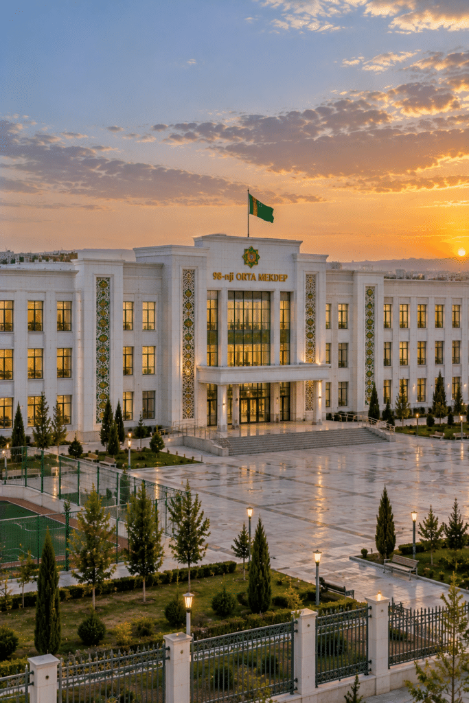 98 Schools ProjectSchool campus · Turkmenistan
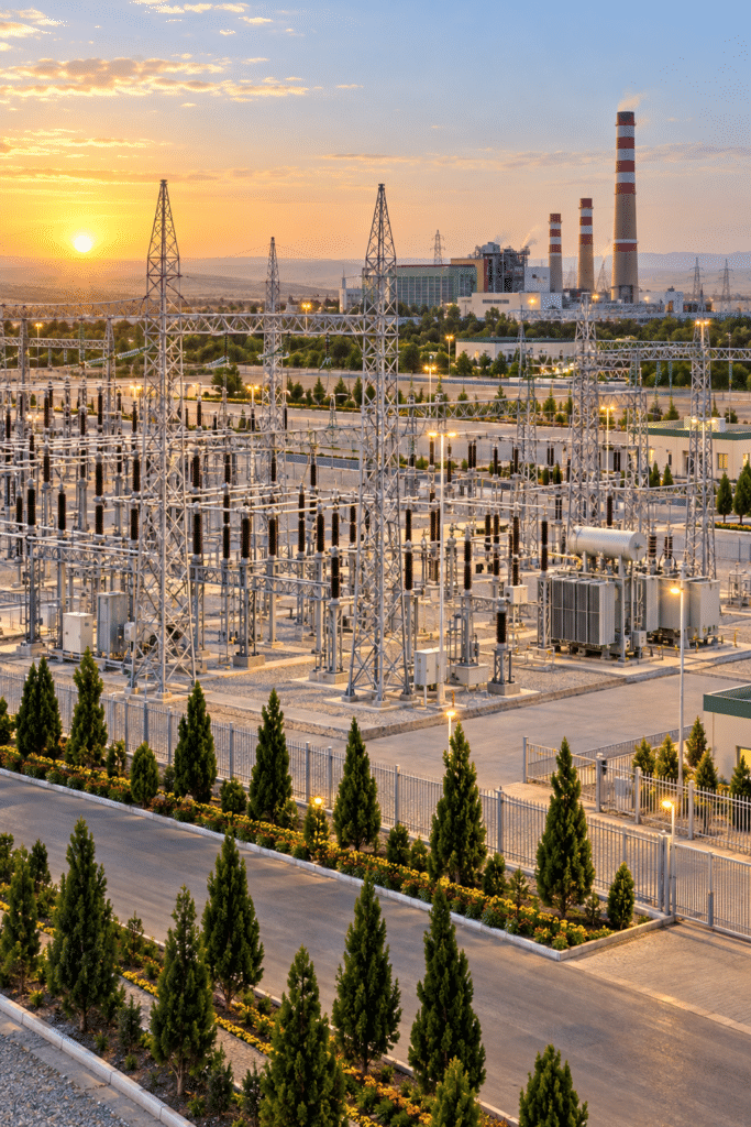 Mary SwitchyardSwitchyard and substation · Mary, Turkmenistan
Do you have a project of a similar scale?
Send us your single-line diagram, your transformer rating or simply your load list. Our engineering team runs the short-circuit and discrimination study and defines the form of separation and busbar cross-section with you.
Request a quotation